| HOME · MOVIES · HIKING · PHOTOS | SITE MAP | ||
It was time to buy a new charger for the stack of NiMH cells I use for portable gear. After reading reviews and recommendations on various battery forums I bought a Maha C9000 charger because of the following features.
It proved to be a great charger with enough status info to keep me happy. It's not perfect though: My biggest knock against the status display is that one has to wait for it to cycle through the four values it gives for each cell. If all that one wants to know is the voltage then one must be patient while waiting for it to come around. The other misfeature is that one can't set parameters for one channel and then assign them to all channels at once; however, if one only wants to charge all cells at 1000 mA then the default is fine.
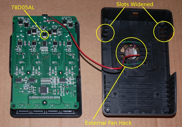
I noticed that the top of the unit just above the postive end of the cells would always heat up. Was it conducted heat from the cells or were there electronics under the cover that were getting hot and heating the cells by conduction? I found some photos online that showed there was nothing inside the unit at that location that could be responsible for the heat but I became suspicious when I saw photos of the bottom side of the circuit board. That's where the power MOSFETs are located. Perhaps they were getting hot and the heat was being conducted to the cells via the positive terminals soldered to the circuit board.
I removed the bottom cover and quickly found the source of the heat problem. It wasn't the MOSFETs; in operation they only became warm, instead it was the 78D05AL voltage regulator. It's used to bring the 12V supply voltage down to 5V for some of the electronics; it became too hot to touch. It's a linear regulator dropping seven volts, which leads to an appreciable power dissipation if there's more than trivial current being drawn. I don't know what the current draw is but that regulator became too hot to keep a finger on. A temperature probe showed 48° but I expect that it was even hotter with the bottom of the case on.
That heat was being sinked by the circuit board, which heated up the positive terminals, which then heated up the cells. The regulator is in the center of the top section of the charger, placing it closest to the center two cells, thus their higher temperature. I had identified the problem, but how to fix it?
The designers of the charger may have compensated for the regulator heating up the charger and cells so I have a nagging worry that the charger's cell temperature profiling could be affected by the unit no longer heating up. However, the fan is only blowing on the bottom of the circuit board. The board has a tight enough fit that there should be little airflow on the top side where the thermistors are located. The fan blows no air across the cells, so they'll still begin to warm up as expected when they become full. The thermistors should detect this. However, all of my cells reach the C9000's 1.47V charging cutoff limit so I haven't been able to test a temperature rise cutoff.
| Copyright © 1996-2011 Toomas Losin | Contact | Disclaimer | ||