| HOME · MOVIES · HIKING · PHOTOS | SITE MAP | ||
For taking extended car trips with lots of electronic gadgets I realized that I needed an inverter to keep all the batteries charged. Canadian Tire had a good sale price for a Motomaster Eliminator 400W model, so I bought one. Not coincidently, this is enough power output to keep my home workstation, monitor, and the bare minimum of network gear running if I need to hook up a car battery in an emergency that lasts longer than my UPS capacity.
I was curious about the inverter's output waveform so I hacked together a voltage divider to use a sound card line input to sample the waveform. Audacity was used to display this waveform.

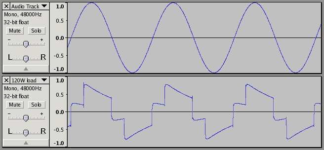
The first waveform is a 60 Hz signal generated by Audacity. It's not a measure of anything but shows what an ideal 60 Hz sine wave should look like. The second waveform is the inverter output sampled while driving a 120W light bulb as a resistive load. Interestingly, an unloaded waveform was found to be identical to the loaded one. Note the ugly glitches at various points.
A careful look at the waveform shows that even after three cycles the phase has measurably slipped with respect to the synthesized 60 Hz signal, so the frequency of the inverter is actually a little bit greater than 60 Hz. Using this to run a clock that uses the line frequency for its reference may not be the best long term idea!
| Copyright © 1996-2010 Toomas Losin | Contact | Disclaimer | ||